Windows and Doors
Aluminium Louvre Window System: Components and Operating Mechanism
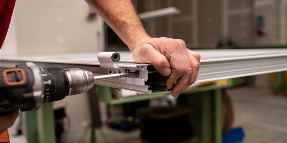
An aluminium louvre window system is a linked mechanical assembly. Its visible blades receive most attention, but reliable operation depends on how pivots, clips, control bars, frame sections and seals maintain alignment. Understanding that load path helps specifiers distinguish a complete system from a collection of visually similar parts.
The broader aluminium louvre specification guide covers supplier selection. This article follows the movement from a user's hand or motor through the linkage, then examines how the frame manages wind, water and optional screens.
From handle movement to blade rotation
A manual handle applies torque to an operator connected to a control bar. The bar links a series of blade carriers. Each carrier rotates around a pivot located in the side jamb, turning every blade by a similar angle. Stops limit excessive travel, while friction or a locking feature holds an intermediate setting.
Small dimensional errors accumulate across the bank. If one carrier is installed out of position, its blade may contact the adjacent edge early, leaving another blade unsealed. Excessive free play can cause rattling under fluctuating wind. Hardware therefore needs compatible blade thickness, accurate spacing and secure attachment rather than improvised substitution.
The frame is both structure and water path
Head, jamb and sill profiles form the perimeter. They transfer wind pressure from blades and hardware into anchors and the surrounding wall. Mullions may divide a large opening into manageable modules. Section depth and internal chambers influence stiffness, hardware space and the route available for collected water.
Rain reaching the blade edges may be deflected outward, caught in channels or drained through weep paths. The sill must remain correctly oriented and unobstructed. Perimeter sealant closes the frame-to-wall joint but should never bridge intended drainage holes. Installation distortion can alter both structural behaviour and drainage falls.
Component interaction checklist
- Blade and clip: Material thickness, edge condition and clip geometry must match.
- Pivot and jamb: Bearings need alignment and enough support to resist repeated cycling.
- Control bar and operator: Travel must rotate all blades without overloading the end stops.
- Seal and overlap: Contact should be consistent across the width when the bank is closed.
- Sill and weeps: Water must have a continuous outward route after entering the frame channel.
- Frame and anchors: Fixings must resist design loads without twisting the operating assembly.
Blade bank geometry
Blade width, vertical pitch and rotation angle determine overlap and free opening. At a near-horizontal open position, the projected obstruction is low, but clips, screens and frame sections still reduce effective area. At partial angles, airflow is redirected and resistance increases. Closed blades need enough overlap and seal compression to limit direct paths.
Longer unsupported spans experience more bending under wind and self-weight. Allowable span depends on blade material, profile, thickness, glass specification and test evidence. Splitting a wide opening with a mullion may be more reliable than extending blades beyond the system's approved range.
Manual and motorised operators
Manual hardware offers tactile feedback and few electrical dependencies. Handle placement should remain reachable and clear of the reveal. A geared operator can increase mechanical advantage but adds components and backlash. Pole operation suits occasional high-level use only when the attachment point is secure and the action can be performed safely.
A motor replaces manual input with an actuator. Concealed installations preserve appearance but require removable access. The actuator needs compatible stroke, torque, duty cycle and environmental protection. Controls may be a wall switch, remote, timer or building automation output. Limit calibration is important: driving beyond the mechanical stop can damage links or compress seals excessively.
Seals, screens and secondary layers
Blade seals can be brush, flexible polymer or formed contact surfaces depending on the system. They reduce uncontrolled leakage and rattling but age under heat, ultraviolet light, dirt and cleaning chemicals. A seal that looks present may no longer make uniform contact.
Insect mesh adds a fine barrier behind or ahead of the louvres. Security mesh uses stronger material, frame sections and anchoring. Neither should interfere with the operator or prevent blade replacement. Because every mesh creates pressure loss, ventilation calculations should use the complete assembly rather than the louvre opening alone.
Combined configurations
Some frames combine a louvre bank with a casement or fixed panel. This can provide everyday ventilation through blades and a larger opening through the casement. The arrangement introduces additional hinges, stays, locks and weather joints. Movements must not collide, and mullions must transfer loads from both functions.
A shop drawing should identify which section operates, opening direction, handle position, screen arrangement and glass or blade specification. The configuration also affects cleaning access. An attractive elevation is not enough; sections and hardware schedules reveal whether the proposed parts can coexist.
Failure behaviour reveals the cause
Blades that close unevenly suggest carrier displacement, linkage wear or frame distortion. A stiff handle may indicate contamination, a bent control bar, overtight seals or misaligned pivots. Rattling points to free play, loose blade retention or inadequate closure. Water at the sill may come from blocked weeps, failed perimeter sealant or pressure exceeding the assembly's capability.
Do not force a resistant operator. Isolate motor power where applicable, inspect visible obstructions and arrange competent service. The louvre maintenance guide provides a practical diagnostic sequence, while the installation guide explains how initial alignment prevents many recurring faults.
Technical FAQ
Why do all louvre blades move together?
Each carrier is connected to a common control bar or linkage. The handle or actuator moves that linkage, rotating the blade pivots through the same travel.
What causes one blade to remain partly open?
Possible causes include a displaced carrier, broken clip, loose blade, worn linkage or frame distortion. The bank should be inspected before the operator is forced.
Does deeper framing always mean better performance?
No. Depth can provide stiffness or hardware space, but tested configuration, section design, anchors, seals and installation determine actual performance.
Can any actuator be fitted to a manual louvre?
No. Stroke, force, mounting, limits and access must match the window system. Retrofitting should follow the system supplier's approved details.