Machine Vision
AOI Lighting and Camera Setup for Reliable Defect Detection
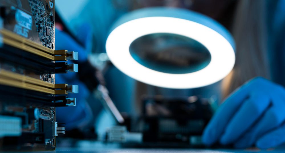
AOI reliability starts before software analysis. If the camera does not capture a clear and repeatable image, the inspection result will not be stable. Lighting, camera position, lens selection, focus, exposure, and mechanical stability decide whether a defect is visible enough for the system to judge. Many AOI problems that look like software problems are actually image acquisition problems.
The goal of lighting and camera setup is contrast. A defect should appear different from a good condition in a way that remains stable across normal product variation. For example, a scratch may need low-angle lighting to become visible. A printed code may need diffuse lighting to reduce glare. A hole, edge, or silhouette may need backlighting. The inspection tool can only measure what the image reveals.
Lighting Geometry
Different lighting geometries reveal different features. Ring lights provide general illumination around the lens. Bar lights can create directional contrast. Dome lights reduce reflections on curved or shiny surfaces. Coaxial lighting highlights flat reflective surfaces. Backlights create silhouettes for measurement. Dark-field lighting highlights raised or surface defects by catching scattered light.
Choosing lighting is therefore a defect-driven decision. Engineers should collect real good and bad samples, then test which lighting makes the defect separate clearly from acceptable variation. In some cases, multi-light inspection is needed because one light reveals presence while another reveals surface condition.
Setup Variables to Control
- Field of view: The area captured by the camera must include all inspected features.
- Resolution: The defect must occupy enough pixels for reliable detection.
- Working distance: Distance affects lens choice, focus, lighting angle, and machine layout.
- Exposure: Short exposure freezes motion but requires enough light intensity.
- Focus and depth of field: Features must stay sharp despite height variation.
- Ambient light: External light changes can disturb inspection consistency.
Camera and Lens Selection
The camera must match the required detail and speed. A higher-resolution camera is useful only if the lens and lighting can provide a sharp image. A faster camera is needed when parts move quickly or when multiple images must be captured in a short cycle time. Interface selection also matters because image data must reach the processor without creating a bottleneck.
The lens controls magnification and distortion. For dimensional inspection, distortion can create measurement error. For small components or fine solder features, magnification and working distance must be chosen carefully. Telecentric lenses may be used when accurate measurement is more important than low cost.
Calibration and Repeatability
AOI systems should be calibrated when measurements are required or when camera position may change. Calibration converts pixels into real units and corrects for lens behavior where needed. Even when the inspection is pass/fail rather than dimensional, repeatability still matters. Loose mounts, vibration, temperature changes, or accidental focus adjustment can change inspection results.
Good setup includes controlled mounting, locked lens settings, protected lighting position, and documented exposure values. The main automated optical inspection guide explains how image capture fits into the complete AOI workflow.
Common Setup Mistakes
A common mistake is using bright light without considering reflection. More light is not always better. Another mistake is relying on auto exposure or auto focus in a production system, which can change the image from part to part. Engineers should also avoid designing around one perfect sample. Real production includes tolerance, dust, surface changes, and handling variation.
Stable AOI setup is an engineering process. It requires testing, documentation, and review when product materials, suppliers, or process conditions change.
Environmental Control
Production environments can disturb image quality. Ambient light from windows, operator lamps, machine doors, or nearby equipment can change the captured image. Dust on a lens cover can reduce contrast. Vibration can soften edges. Heat can change focus slightly when lenses, mounts, or machine frames expand. These effects may be small, but AOI systems often inspect small details where small changes matter.
Good systems use light shielding, rigid mounts, clean inspection windows, and periodic image checks. If a machine is installed near a bright doorway or under changing daylight, the lighting design should isolate the inspection area from those changes.
Image samples should be saved during commissioning. A reference set of good images, failed images, and borderline cases helps engineers compare future machine behaviour. When inspection performance changes, these saved images make it easier to identify whether the issue is lighting, focus, product variation, or recipe tolerance.
Setup Documentation
Lighting and camera settings should be documented in enough detail for maintenance teams to restore the system after cleaning or part replacement. Useful records include lens model, aperture, focus position, working distance, light type, light angle, exposure, gain, trigger delay, and sample images. Without these records, small changes can be treated as software problems even when the real cause is a shifted bracket, ageing light, or adjusted lens.
Technical FAQ
Why is lighting more important than camera resolution?
Resolution gives detail, but lighting makes the defect visible. A high-resolution image with poor contrast may still fail inspection.
Should AOI use automatic exposure?
Usually no. Fixed exposure is preferred for production repeatability unless the system is specifically designed to control exposure safely.
When is backlighting useful?
Backlighting is useful for silhouette measurement, edge detection, holes, outlines, and presence checks where shape contrast is important.
What causes glare in AOI images?
Glare is caused by reflection from shiny surfaces, light angle, lens position, and surface geometry. Diffuse or angled lighting may reduce it.